Tailgate Switch |
 |
| TITLE |
+ |
- |
| FILE NAME |
+ |
- |
| DATE |
+ |
- |
|
|
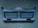
1. Tailgate internal trim – 3195 viewsStart by removing the two screws from the hand holds
|
|
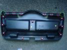
2. Tailgate internal trim - inside – 3473 viewsNotice all the clips which you pull apart to take it off.
Also notice the arrangement of the fins at the upper corners, these engage in the upper trim of the tailgate and are a bit fiddly to align when reassembling it.
|
|
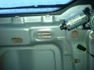
3. Nuts which hold the number plate light housing in place (set 1) – 3793 viewsUse a 10mm socket on a short extension bar to remove them.
It's also prudent to have a magentic pickup to hand to stop them disappearing into the tailgate as they come off!
Don't forget to unplug the wiring to the switch and number plate lights.
|
|
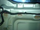
4. Nuts which hold the number plate light housing in place (set 2) – 3248 viewsUse a 10mm socket on a short extension bar to remove them.
It's also prudent to have a magentic pickup to hand to stop them disappearing into the tailgate as they come off!
There's 6 nuts in total to remove.
Once they are off, remove the number plate light and tailgate switch housing - I found it a little stiff and had to push from the inside on the studs where the nuts had been removed from.
|
|
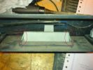
5. The tailgate switch in situ – 3718 viewsPush the clips in at each side to release it from the number plate light housing and push it down and out.
|
|
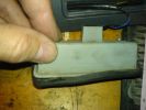
6. Remove the rubber cover from the switch assembly – 3385 viewsJust pull it off.
|
|
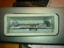
7. The tailgate switch disassembled – 4220 viewsYuk, needs cleaning.
|
|
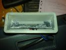
8. The tailgate switch disassembled – 3740 viewsClean the crud out with something suitable - I used household limescale remover as the crud seemed like limescale.
Work the flappy bit back and forth until it moves freely.
|
|
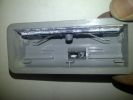
A. Partially removed old switch – 1873 viewsI found a punch that was just the right size to dismantle the switch in situ. It's supposed to come out towards the camera in this shot but it came out the other way in pieces.
|
|
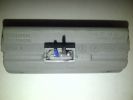
B. Old switch disconnected, partially extracted – 1862 viewsRun a sharp knife between the grey plastic and the black part of the switch to free it off. Don't need to be too accurate, the switch is not coming out in one piece...
|
|
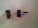
C. New switch and what remains of the old switch – 1756 viewsThe new switch I chose was basically the same size although it had side lugs and a screw loop. The screw loop on the end easily hacksawed off and the side lugs just filed off. What was left was exactly the same size as the old one...
I used a \\\"Omron D2HW C201H\\\" sealed microswitch, cost just over £4 on a popular auction site. There are other versions of the switch around but they had pins not solder loops for attaching the wires to.
|
|
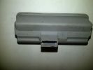
D. The switch holder with the switch removed – 1316 views
|
|
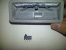
E. New swich ready for insertion – 1380 viewsIt\\\'s now easy to see how the switch just pushes in from this side once soldered, and sits against the lugs.
|
|
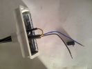
F. Ready to solder the new switch – 1385 viewsThe new switch pushes backwards into the hole so it is necessary to run the cables thru the moulding before soldering them!
Make sure that you connect the wires to the normally open connection pair otherwise you will be sure to encounter some weird behaviour!
(the looped back yellow wire was like that to keep it out of the way)
|
|
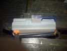
G. New switch glued in place with 2 part epoxy glue – 1341 viewsI used a knife to put some glue around the switch hole itself and pushed it in. I then filled the back of the switch with glue, covering the connections completely to avoid any chance of moisture ingress.
Then clipped the cables as shown whilst the glue dried so that they sit in their original orientation.
|
|
|
|
|

 Forum-Gallery-Shop-Sponsors


 Forum-Gallery-Shop-Sponsors
